Electronic features for electronics type H
| Electronics Type H | ||
|---|---|---|
| Supply voltage | +5 ± 0.2 V | |
| Current consumption max.* | 250 mA | |
| Laser output power potentiometer | < 1 - 100 % | |
| TTL modulation logic: TTL high | Laser ON | |
| TTL or analog input: open or low | Laser OFF | |
| Analog control voltage Pmin to Pmax | 0 ... 2.5 V | |
| analog | TTL | |
| Max. modulation frequency* | 100 kHz | 100 kHz |
| Modulation input resistance [Ohm] | 22 k | 22k |
| Modulation delay ON/OFF* | 2/0.3 | 1.5/0.1 |
| Rise/ Fall Time [µs]* | 1/1 | 1/1 |
| Cable Type | LiY(st)CY 4x0.08 mm² | |
| * Typical values. The actual values depend on the chosen laser diode and may differ slightly in reality. Please refer to the individual laser web pages or the individial laser manuals for details. | ||
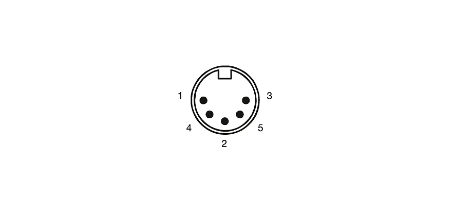
Pin-out
Circular connector Lumberg SV50 (male, IEC 61076-2-106) for power supply and external modulation (pins Uanalog and UTTL).
Cable shielding and casing are connected and are galvanically isolated from the laser diode and the electronics.

Pin-out Electronics Type C/P/H
| Cable | Pin | Function | |||||
|---|---|---|---|---|---|---|---|
| black | 1 | GND | |||||
| red | 2 | + 5 V | |||||
| brown | 3 | Uanalog | |||||
| orange | 4 | UTTL | |||||
| 5 | n.c. | ||||||
| shield | case | functional earth | |||||
Modulation
The laser has two AND-wired modulation input channels, Uanalog and UTTL.

Connecting analog voltage
The input for analog modulation allows applying an analog voltage Uanalog in a range from 0 V to 2.5 V) which allows a linear control of the laser output power from Pmin (Pmin is on the order of < 1% of Po) up to the maximum power given by the potentiometer setting.

Timing diagram
The laser is OFF in case of an open modulation input. If only one modulation input channel is used, the other has to be set to +5 V.