Bright and dark-field illumination
Bright-field illumination
The light is directed straight onto the surface of the test plate. Within the sensor head the beam path is collinear with the beam path of the image. In this configuration the illumination is most efficient. The high image contrast results from the direct reflection of light on the flat areas of the test plate which appear light and textured and structured edges produce darker areas in the image.

Beam Path of Bright-field illumination
Collinear beam path in the sensor head.

Principle of Bright-Field Illumination
Direct reflection of light on the flat areas of the test plate which then appear light on the sensor. Textured and structured edges reflect the light away from the camera and appear dark.
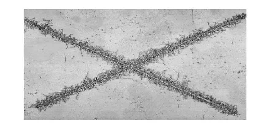
Example: Corrosion Test Panel imaged with bright-field illumination
High contrast image. Flat, usually coated areas of the test plate appear light in the image. The textured and structured edges of the filiform underfilm corrosion and damaged coated areas produce darker areas in the image.
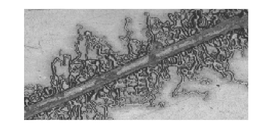
Zoom into the image
Zoom into the image
Dark-field Illumination
With dark-field illumination the light is directed onto the sample at an angle. The light that is directly reflected from the sample surface no longer reaches the camera aperture directly. Only stray light from reflection on edges and damaged, structured areas is detected. Due to the direction dependent illumination the structures typically appear embossed and like a relief.

Beam Path of Dark-field illumination
The light is directed onto the sample at an angle.

Principle of dark-field illumination
The light that is directly reflected from the sample surface is reflected away from the camera and no longer reaches the camera aperture directly. These areas appear dark in the image. Only stray light from reflection on edges and damaged, structured areas is reflected into the camera and is detected. These areas appear bright.
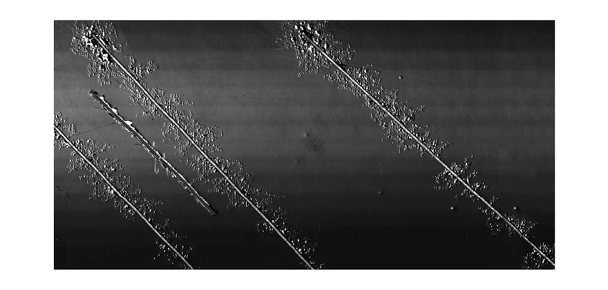
Example: Corrosion Test Panel imaged with dark-field illumination
The light from the flat parts of the sample is reflected away from the camera and no longer reaches the camera aperture directly. Only stray light from reflection on edges and damaged, structured areas is detected. For extensive underfilm corrosion with flatly rising edges this setup is most beneficial. The structures appear embossed and like a relief.
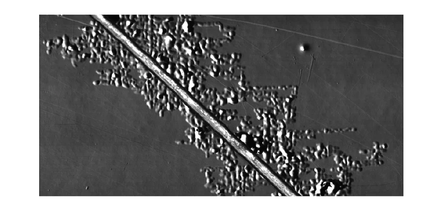
Zoom into the image
Zoom into the image