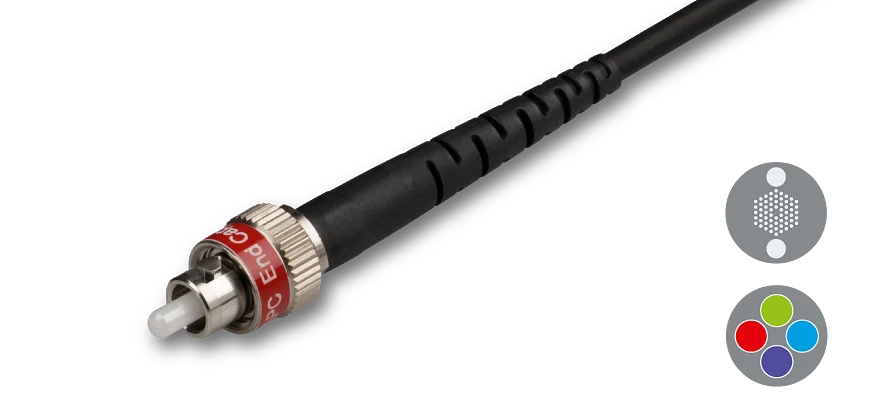
Endlessly single-mode, photonic crystal fiber cables series PCF-S with Gaussian intensity profile and low-stress fiber connectors with end caps.
Fiber
The fiber is a endlessly single-mode PCF fiber,they have a core diameter of 5 µm. The mode-field diameter MFD is almost independent of wavelength. The effective numerical NAe2 is measured for each connectorized fiber by Schäfter+Kirchhoff. The special broadband fiber has an operational wavelength range of 370 nm - 1550 nm.
Fiber Cable
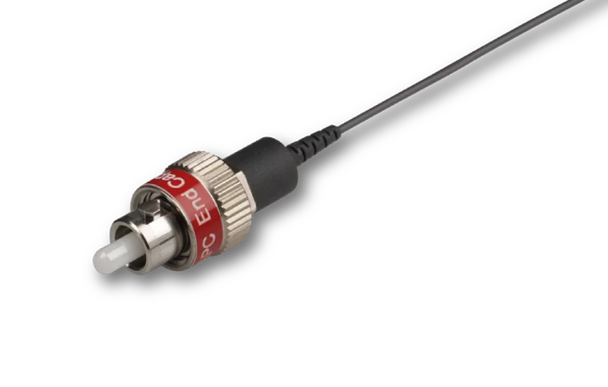
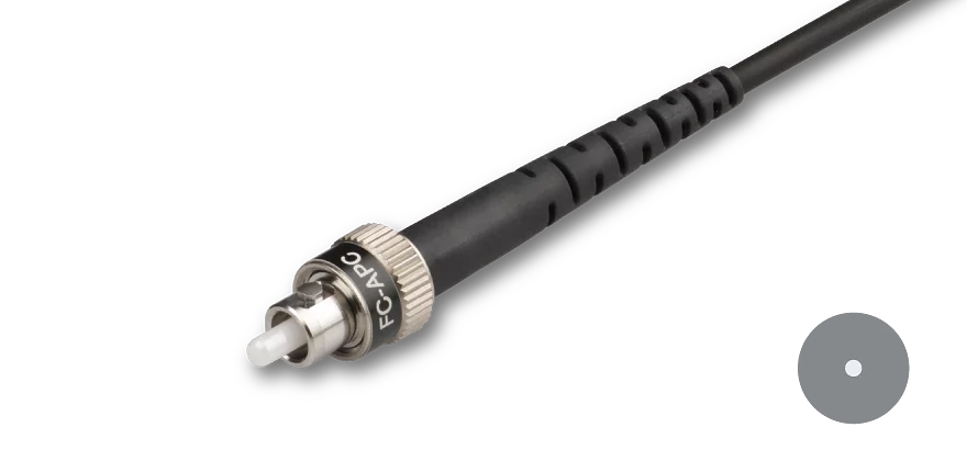
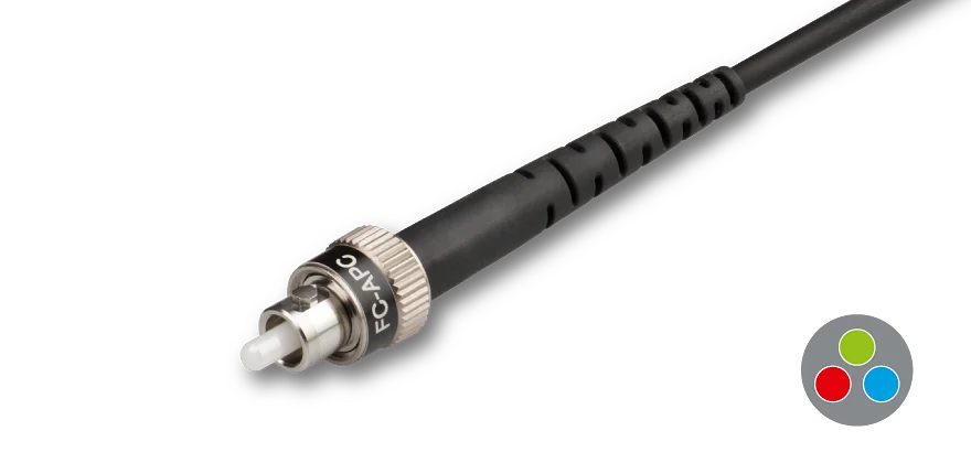
The fiber length can be customer-specified (there is a minimum fiber length). The single-mode PCF fiber cables are offered as Ø 900 µm buffer in black, or a Ø 3 mm cable in black with Kevlar strain-relief.
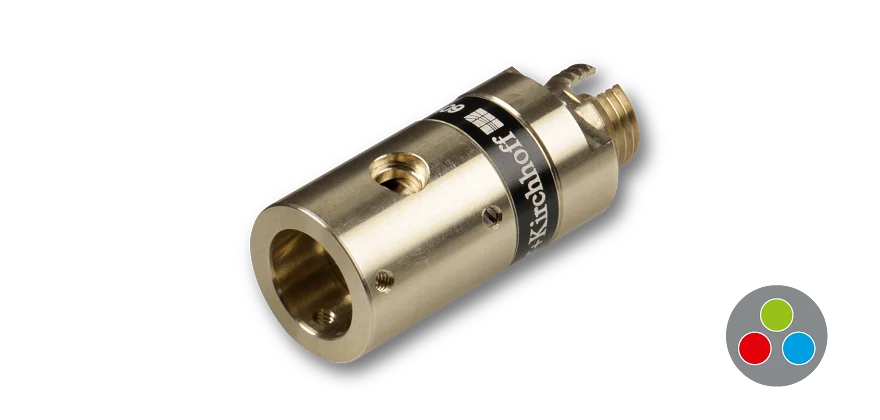
Fiber Connectors
For each fiber end the fiber connector type can be chosen (FC PC with 0°-polish or FC APC with 8°-polish). The fiber connectors of type FC assembled by Schäfter+Kirchhoff have an alignment index (key). The wide key (type "N") fiber connector has an alignment index (key) of 2.14 mm width. The narrow key (type "R") fiber connector has an alignment index (key) of 2 mm width. Special fiber connectors are available so that the fiber cable is vaccum compatible down to 10-7 mbar (only Ø 900 µm buffer fiber cables).
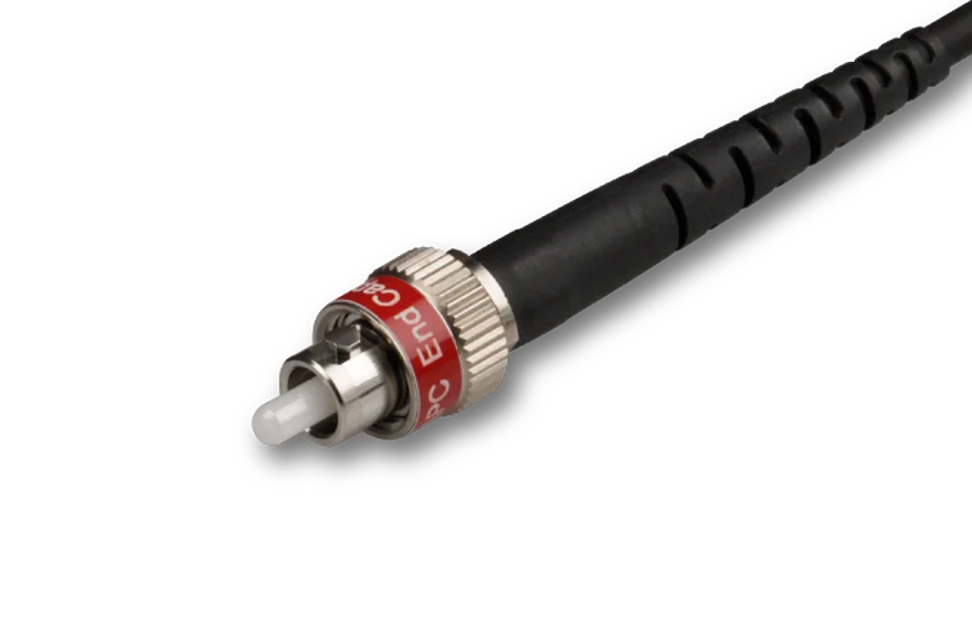
End Caps
The fiber connectors of all PCF fiber cables are equipped with an end cap. This means that a short piece of coreless fiber (< 300 µm) is spliced onto the polarization-maintaining PCF fiber. The end cap seals the microstructure of the fiber and allows for an easy cleaning of the end-face. Additionally it also reduced the power density at the fiber end-face.
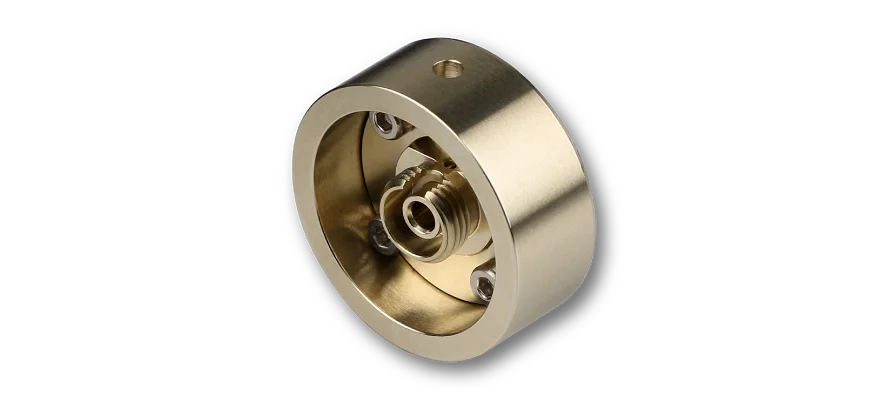
Amagnetic fiber connectors
For FC PC or FC APC type connectors amagnetic versions completely made of titanium can be selected. Those connectors have a ceramic ferrule.
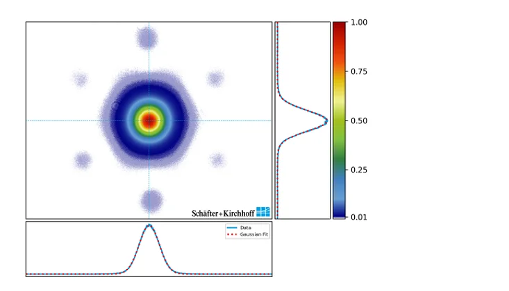
Beam profile
Photonic crystal fibers have many unique properties due to their special microstructure. Of course, this is also visible in the beam profile (see figures on the right). The central spot (zero-order) is almost perfectly Gaussian. Its overlap integral with a 2D-Gaussian function is above 99 %. The hexagonal structure of the beam profile can therefore be neglected in most cases. The higher orders of the beam profile are strongly suppressed and remain below the 1 % level compared to the zero-order intensity. The approximation of a Gaussian like beam shape is therefore more than sufficient for most applications.