Single-mode Fiber Cables

Single-mode fibers series SMC with Gaussian intensity profile

FC-APC-3
FC-APC-1
Representative product images. Individual product images are found on the individual product pages.

Features

Single-mode fiber cable with Gaussian intensity distribution and low-stress fiber connectors.
  • Cut-off wavelengths from 360 nm to 1300 nm
  • Wavelengths covering altogether 360nm to 1650 nm - each fiber with an operational wavelength range of about 100-300 nm.
  • Special broadband fiber RGB with an operational wavelength range 400-680 nm
  • Pure Silica core fibers with low attenuation for wavelengths < 460 nm
  • Measured values for fiber NA: NAe2
  • Special fibers with small NA for smaller power density in the fiber core
  • Fiber patch cable available with Ø 900 µm buffer or as Ø 3 mm Cable with Kevlar strain-relief
  • Customer-specified connectors type FC, AVIM (comp. to LSA), E2000 with  0°-polish or 8°-polish
  • Amagnetic titanium connectors for connectors of type FC PC or FC APC
  • End caps for a smaller power density at the fiber end-faces

Single-mode fiber

Description

Single-mode fiber cable with Gaussian intensity distribution and low-stress fiber connectors.

Fiber
The fiber is a single-mode fiber, defined by its NA and its cut-off wavelength. The nom. NA is specified by the fiber manufacturer. Additionally the effective numerical NAe2 is measured for each fiber batch by Schäfter+Kirchhoff. Cut-off wavelengths range from 360 nm to1550 nm and the fibers altogether cover a wavelength range of 360nm to 1800 nm. Each fiber has an operational wavelength range of about 100-300 nm. Besides the nominal cut-off wavelength λco, Schäfter+Kirchhoff also offers measured data for the cut-off wavelength for each individual fiber cable.
Some fibers have special features e.g.

  • Pure silica core for long-term stable low attenuation and high transmission for < 460 nm
  • Special fibers with extra low NA that leads to a lower power density in the fiber core compared to a standard fiber with standard NA. The maximum power level (described by the Brillouin threshhold) that can be transmitted in the fiber is shifted to a higher value. Please note that there are other limiting factors e.g. concerning the fiber end faces.

Fiber Cable
All fiber lengths can be customer specified. The single-mode fiber cables are offered as Ø 900 µm buffer in black, or a Ø 3 mm cable in black with Kevlar strain-relief.
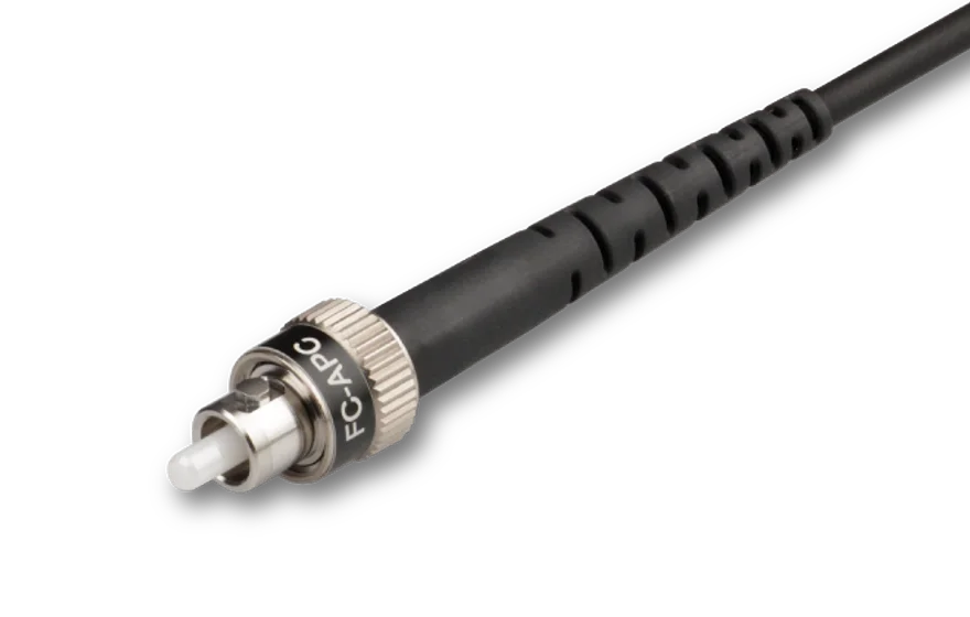
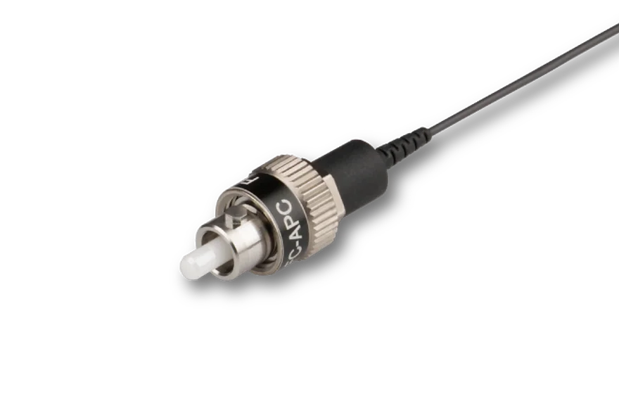
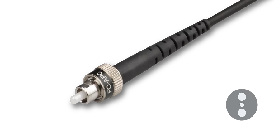
Fiber Connectors
For each fiber end the fiber connectors can be selected from a wide range of connector types (FC, AVIM (compatible with LSA), E2000) with 0°-polish or 8°-polish. All fiber connectors of type FC assembled by Schäfter+Kirchhoff have an alignment index (key). The wide key (type "N") fiber connector has an alignment index (key) of 2.14 mm width. The narrowe key (type "R") fiber connector has an alignment index (key) of 2 mm width. Special fiber connectors are available so that the fiber cable is vaccum compatible down to 10-7 mbar (only Ø 900 µm buffer fiber cables) or for core-centred fibers.

End Caps
The fiber connectors can be equipped with an end cap connector. This means that a short pice of fiber (< 300 µm) without a core is spliced onto the single-mode fiber. Without a fiber core to confine the beam, the mode field diameter of the beam already starts to diverge within the fiber end cap, significantly reducing the power density at the fiber end-face.

Amagnetic fiber connectors
For FC PC or FC APC type connectors amagnetic versions completely made of titanium can be selected. Those connectors have a ceramic ferrule.

FAQ

  • Connector Type FC PC and FC APC
    • How do I attach a fiber cable?

      1. To prevent damage to the sensitive fiber end-face, always insert the fiber connector`s ferrule at an angle, with the connector key properly aligned to the receptacle notch.
      2. When the ferrule tip is safely located in the inner cylinder of the receptacle, align the connector to the receptacle axis and carefully introduce the connector into the fiber coupler.
      3. Then, orient the connector key in a way that it is pressed gently onto the right-hand side of the receptacle notch ("right-hand orientation rule").
      4. Gently screw on the connector cap nut onto the receptacle until it is finger-tight.
      5. Gently tighten the fiber grub screw to reduce the free play of the ferrule in the receptacle.

    • What is the "right-hand orientation rule"?

      When the ferrule tip is safely located in the inner cylinder of the receptacle, align the connector to the receptacle axis and carefully introduce the connector into the fiber coupler. 

      Then, orient the connector key in a way that it is pressed gently onto the right-hand side of the receptacle notch.

      The tightened grub screw and the "right-hand orientation rule" for the connector, ensure a high reproducibility in mode field position and angle, which is especially important for attaching and reattaching polarization-maintaining fibers reproducibly.

    • Can I attach a narrow key fiber cable to a fiber coupler with a wide key receptacle?

      Yes, you can- without any problem. Simply adhere to the "right-hand orientation rule".

      Generally, with any FC PC or FC APC type connector there is a freeplay when inserting the fiber into the fiber coupler. The free play in between the connector ferrule and receptacle is only a few microns, but necessary for inserting the ferrule without force. There is a difference between the receptable and key width for wide key (2.14 mm) and narrow key (2.0 mm) fibers. If you follow the so-called "right-hand orientation rule" you can reproducibly attach and reattach even PM fibers with narrow key receptacle to fiber couplers with wide key receptacle without difficulty.

      "Right-hand orientation rule":

      When the ferrule tip is safely located in the inner cylinder of the receptacle, align the connector to the receptacle axis and carefully introduce the connector into the fiber coupler. Then, orient the connector key in a way that it is pressed gently onto the right-hand side of the receptacle notch. The tightened grub screw and the "right-hand orientation rule" for the connector, ensure a high reproducibility in mode field position and angle, which is especially important for attaching and reattaching polarization-maintaining fibers reproducibly.


    • Can I use an end cap fiber with a mating sleeve?
      Since the radiation has already started to diverge within the end cap, a simple mating is no longer possible. Please use a fiber-to-fiber coupler in this case.
  • What is the minimum bend radius for my fiber cable?
    • Do you have a Ø 900 µm cable?
      If yes, then the min. bend radius is 15 mm. More information can be found here.
    • Do you have a Ø 3 mm cable?
      If yes, then the min. bend radius is 40 mm. More information can be found in the drawing here.

Accessories

Bulkhead Fiber Adapters
Fiber Adapters without Optics
FCCT01
Fiber connector cleaning tool