Features
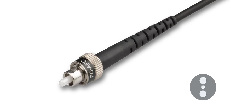
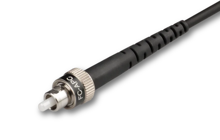
Multimode fiber cable with customer-specified fiber connectors.- Wavelength ranges UV/VIS or VIS/NIR
- Core diameters 50 µm - 300 µm
- Fiber patch cable available with buffer or as Ø 3 mm cable with Kevlar strain-relief
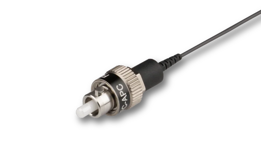
- Customer-specified connectors type FC, DIN or AVIO, E2000, ST (only 0°-polish), or F-SMA (only 0°-polish) with 0°-polish or 8°-polish
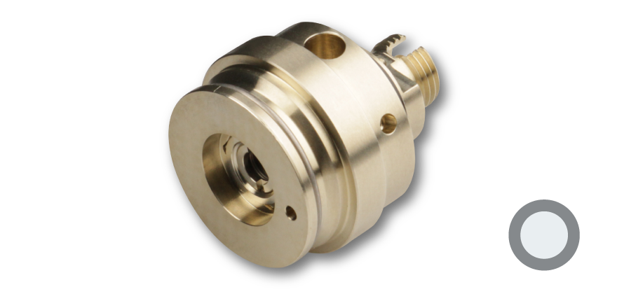
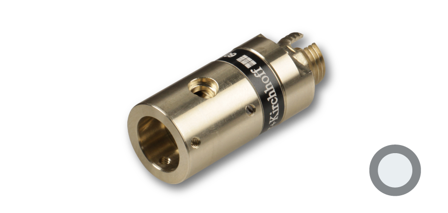
- Amagnetic titanium connectors for connectors of type FC PC or FC APC