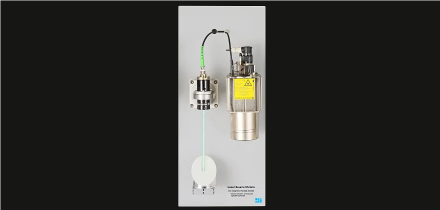
A 51nanoFI beam source that can be switched between two different states, non-stabilized (without RF-modulation) or stabilized (with RF-modulation), is used as a fiber-coupled laser source. The radiation is split using a 50/50 fiber-optical beam splitter.
51nano: General information
51nano-S
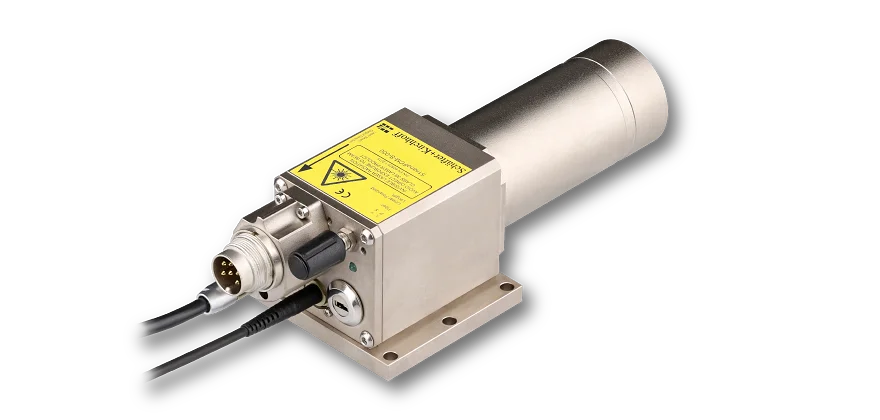
The fiber-coupled low noise laser suorces type 51nano from Schäfter+Kirchhoff exhibit reduced power noise and reduced coherence length . The low noise (typ. < 0.15 % of Po (RMS, Bandwidth < 1 MHz)) and lack of mode hopping make these laser sources ideal for particle measurements or advanced medical and biotechnological applications.
- Low noise laser module (typ. < 0.15 % of Po (RMS, Bandwidth < 1 MHz))
- Reduced coherence
- Mode hopping free laser operation
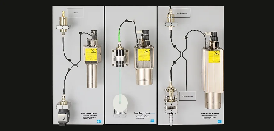
Demonstration setups
51nano
Exhibition setup
- First Setup:
- 1. Demonstration of reduced power noise
- 2. Demonstration of reduced interference
- Second setup:
- 3. Demonstration of reduced speckle contrast
- Third setup:
- 4. Spectrometer
- 5. Fabry-Perot interferometer as application sample
Mode hopping
Conventional single-mode laser diodes are semiconductor lasers and usually operate on one favored longitudinal mode. However, the semiconductor laser material exhibits a temperature dependency, which alters the gain profile and refractive index so that the diode jumps between different longitudinal modes.
This mode hopping causes the output wavelength to jump rapidly by a few picometers. For single-mode diodes that are not stabilized, the output power can change erratically by as much as 3%. This is not relevant for many applications but is relevant for some applications.
Power noise and mode hopping are eliminated in the low noise laser diode module by modulating the current of the laser diodes at high frequency. This RF-modulation excites numerous longitudinal modes of emission while simultaneously lowering signal noise significantly, to typ. <0.15 % RMS of Po.
This induced broadening of the spectrum, in a controlled and stable way, has the added advantage of considerably reducing the coherence length of the laser beam which. In some cases this can also reduce laser speckle contrast and prevent interference patterns.
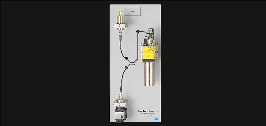
First Setup: 1. + 2. Demonstration of reduced power noise and reduced interference
51nano
Exhibition setup
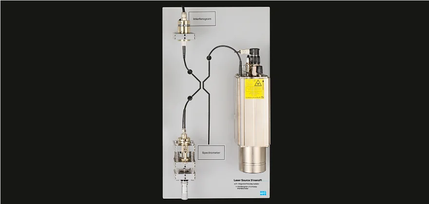
Image of the exhibition setup:
In order to illustrate the reduction of power noise, the 51nano is coupled to a fast photo diode, the other part of the radiation is guided to a flat camera sensor.
1. Demonstration of Low Noise
A common laser diode beam source shows a stochastic power noise resulting from, for example, an external cavity between the laser diode and its fiber coupling.
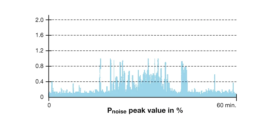
With RF modulation and in normal 51nano operating mode the laser diode is stimulated to emit many modes simultaneously, which leads to the suppression of mode hopping and mean laser power is constant with noise typ. < 0.15 % of Po (RMS, Bandwidth < 1 MHz). Peak noise values exceed 1 % for a standard laser diode.
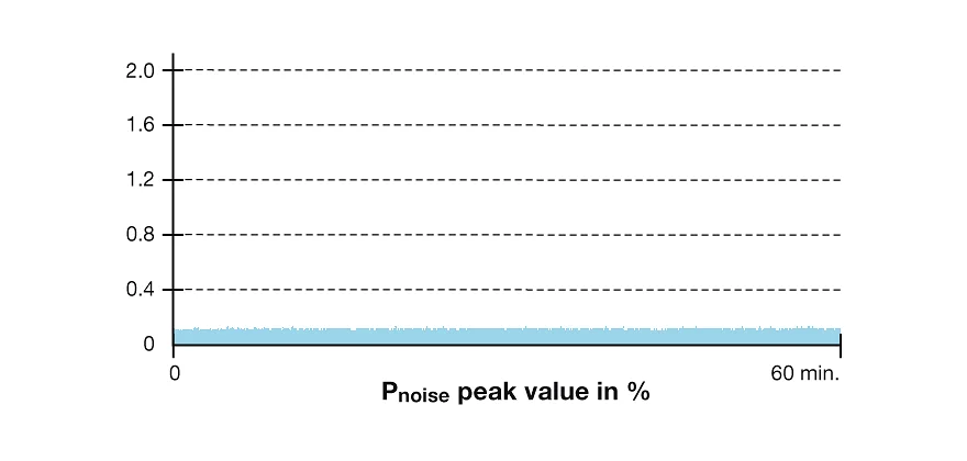
Low noise
51nano
The RF-modulation results in a constant mean laser power.
Power noise typ. < 0.15 % of Po (RMS, Bandwidth < 1 MHz).
LD with noise
Standard laser
Power noise from a laser diode module.
Mode hopping increases the power noise.
2. Demonstration of reduced Interference
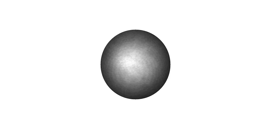
The collimated laser beam of a common fiber-coupled laser source is recorded directly using a flat camera sensor. Its protection window leads to a disturbing interference pattern visible in the collimated beam using a standard laser diode, as a result of internal reflection within the protective glass window of the detector in a CCD area scan camera and interference betwen these reflections.
Since the coherence length of a low noise laser diode module is less than the thickness of the glass the interference is eliminated.
No interference
51nano
Intensity distribution of a laser spot at a camera sensor. No interference patterns, despite the camera sensor protection window.
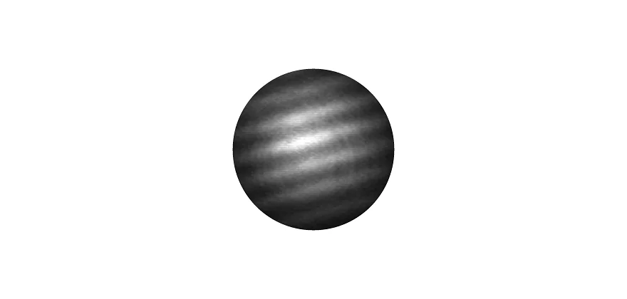
LD interference pattern
Standard laser
The laser spot recorded directly using a camera sensor, with its protection window generating a disturbing pattern of interference.
Second setup: 3. Reduced speckle contrast
51nano
Exhibition setup
The fiber-coupled laser source is connected to a collimator with a large collimated beam diameter, and the collimated beam is directed to a piece of paper.
3. Demonstration of reduced speckle contrast
Speckle arises from multiple interference, e.g. diffuse reflection of laser radiation on optically rough surfaces (> λ/4). The speckle contrast and size generally depends on
This means a general statement that low coherence automatically leads to less speckle is not possible.
- Spot size
- Size of the aperture of the optics
- Measurement geometry
This means a general statement that low coherence automatically leads to less speckle is not possible.
- For thicker laser lines and larger laser spots when using a fully coherent (standard) laser source, the laser speckle contrast is 1 and there are areas of zero intensity within a laser spot. For a 51nano laser source the emission from multiple laser modes results in a reduced coherence length, and the speckle contrast and size are also less.
- For smaller laser spots this benefit is less relevant and there might be little to no difference in speckle behaviour.
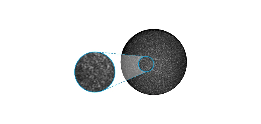
Reduced Speckle
51nano
Low speckle contrast due to reduced coherence length in a large laser spot. Note that speckle contrast and size generally depend on factors such as spot size and the aperture of the optics.

LD Speckle
Standard laser
A standard laser diode module produces a large laser spot with speckle. Note that speckle contrast and size generally depend on factors such as spot size and the aperture of the optics.
Third setup: 4.+ 5. Spectrometer and Fabry-Perot interferometer as application sample
51nano
Exhibition setup
A 51nanoFI beam source that can be switched between two different states, non-stabilized (without RF-modulation) or stabilized (with RF-modulation), is used as a fiber-coupled laser source. The radiation is split using a 50/50 fiber-optical beam splitter. One portion is directed to a spectrometer to analyze the spectral power density of the source. The other part is used for the Fizeau interferometer.
4. Spectrometer
Without RF-modulation, the laser jumps stochastically between several emitting modes. Using RF-modulation, numerous modes are excited within the gain profile of the resonator, producing a broad spectrum with about 1.5 nm FWHM (full-width at half-maximum).
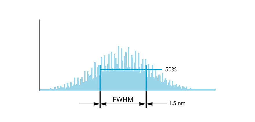
LNC broadened spectrum
51nano
Broadened spectrum (~1.5 nm FWHM) with reduced coherence length (0.3 mm) as a result of using RF-modulation.
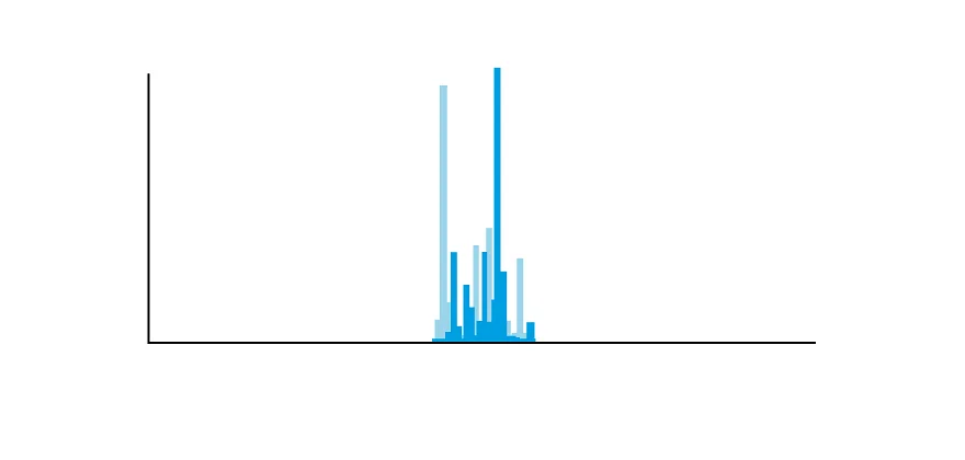
Mode-hopping
Standard laser
Mode hopping: temporal jumps between modes. The short-term coherence of individual modes is >1 m, but effective coherence length is smaller.
5. Fabry-Perot interferometer as application sample

Fabry-perot scheme
Fabry-Perot interferometer: Schematic setup
The part of the 51nano laser radiation not guided to the spectrometer is guided to a mirror under piezo-control that oscillates sinusoidally. This mirror represents e.g. a cantilever in AFM. Fresnel reflection causes a small part of the radiation to be reflected at the fiber end-face, which interferes with the light that is reflected by the oscillating mirror (fiber-optic Fabry-Perot Interferometer).
The interference signal is then split again at the fiber-optical beam splitter. The part of the signal coming back to the laser source is suppressed by an integrated Faraday isolator that serves as an optical diode, while the other part is detected by a photodiode. A specifically developed transimpedance converter then transforms the photo signal into an oscilloscopic voltage signal.
The stabilized beam produced by the 51nanoFI laser diode exhibits a highly stable interferometer signal with low noise. Without RF-modulation, mode hopping and undesirable interference result in signal noise that varies stochastically.

Fabry Perot Oszillogramm
51nano
Fabry-Perot interferometer signal: Stable signal without any disturbing interferences.

Fabry Perot Oszillogramm
Standard Laser
Fabry-Perot interferometer signal: Instable signal with disturbing interferences.