Features
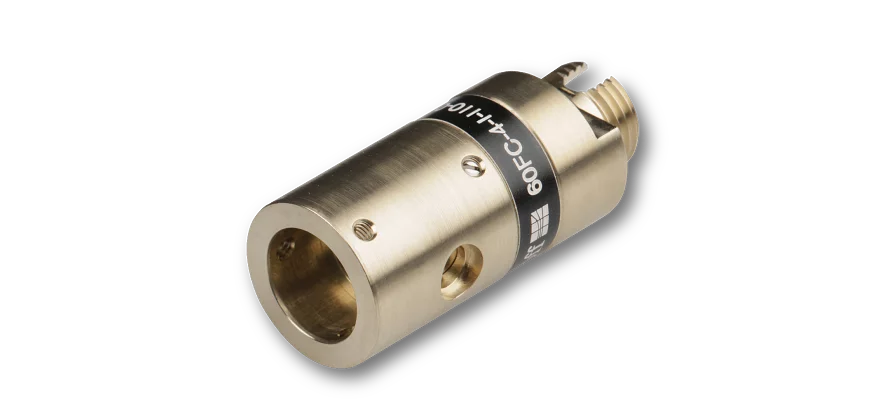
Casing feed-through type CFT with integrated fiber cable- For bore hole Ø 10.7 mm
- Integrated multimode fiber cable MMC
- Fiber cables with core diameters Ø 50 µm - 600 µm
- Different connector types
with multimode fiber cable
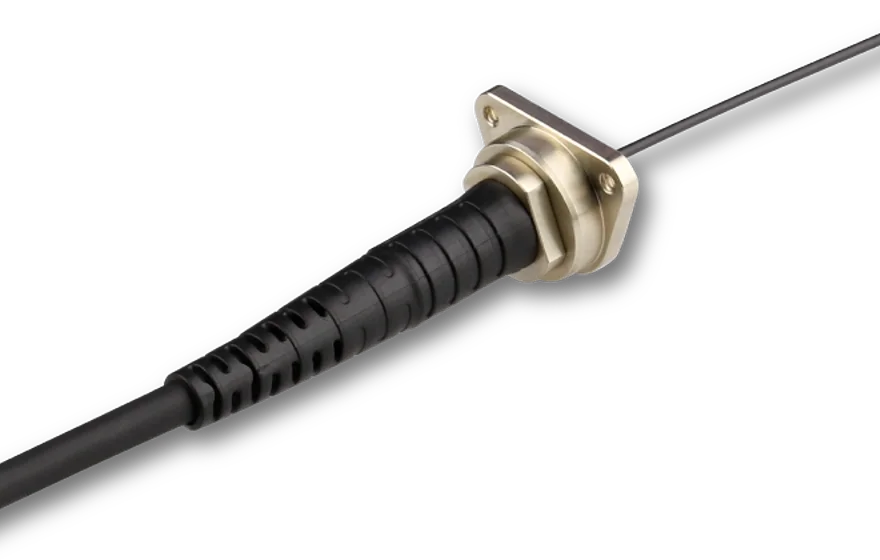
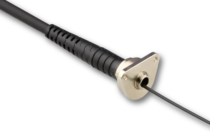
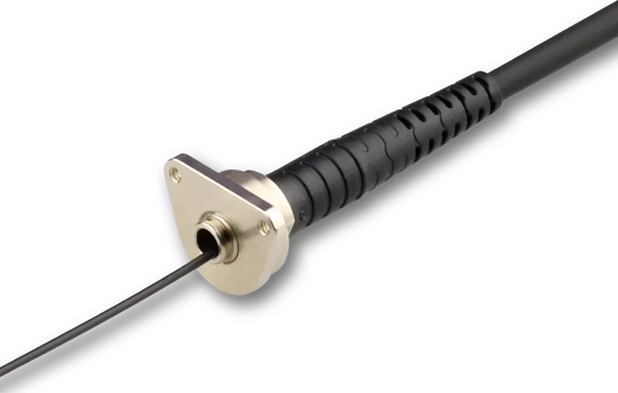
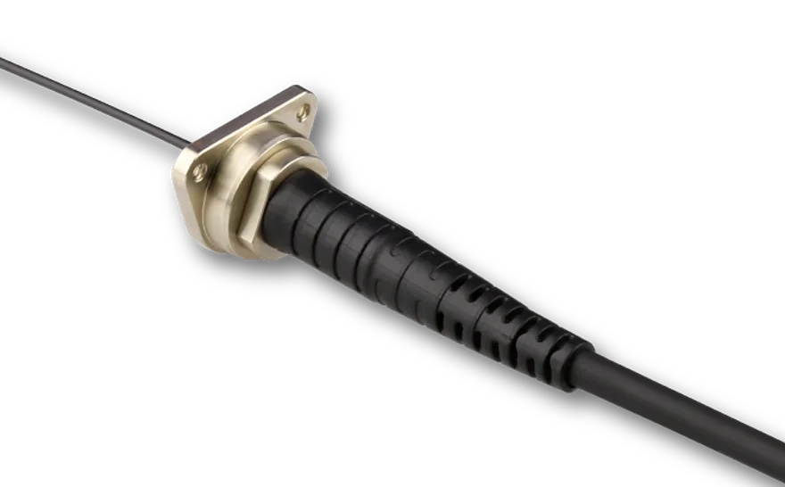
The fiber cables with casing feed-through made by Schäfter+Kirchhoff are equipped with with multimode fiber cables with core diameters Ø 50 µm - 600 µm. The casing feed-throughs type CFT are installed by threading the outer part of the fiber cable from the inside of the casing through the through hole.They are designed for casings with a Ø 10.7 mm through hole.
End-to-end fiber cable
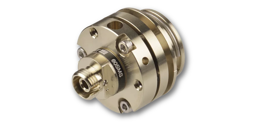
All vacuum feed-throughs are supplied with a non-exchangable, continous, end-to-end fiber cable. That means there is no additional fiber connection (mating) at the vacuum flange.
The benefit is no additional coupling losses due to mating (especially important for small core diameters).
Multimode fiber cable
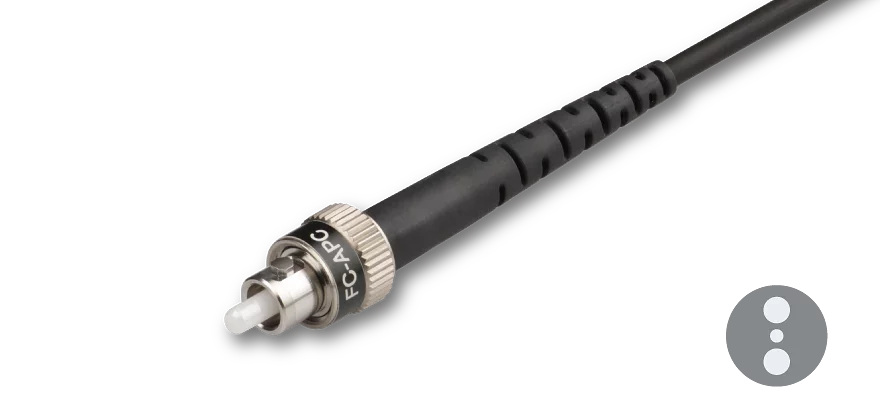
Inside the casing, the fiber cables are equipped with Ø 900 μm buffer made of Hytrel, Nylon or Tefzel. The part of the fiber cable outside the casing, has a Ø 3 mm cable with Kevlar strain-relief with bend protection both at the fiber connector and the flange.
As an option the connector can be made of amagnetic Titanium (connector type FC only).
Please refer to the individual MMC fiber cable pages for all fiber options. The connector types are described in detail here.
How to order
For a specific feed-through please contact Schäfter+Kirchhoff. We additionally need information on:
An example configuration can be found here.
The beam profile exiting a multimode fiber is strongly dependent on how the light interacts within the fiber and is often very different from that of a single-mode fiber - it might even change with time and fiber position. For a good, symmetric, and “super-Gaussian” distribution of light exiting the multimode fiber (aside from laser speckle), it is important that mode mixing has occurred within the fiber or that multiple modes have been excited from the start when coupling in.
For example, if you couple light into the fiber from a single-mode laser source, only a few modes will be excited. If you then change the fiber position or touch the fiber, the ex-fiber beam profile can change rapidly over time because different modes are excited that may not have a symmetric, Gaussian-like output (e.g. donut modes).
To avoid this, you can either make the multimode fiber longer (to increase mode mixing as it passes through the fiber) or coil the fiber with a smaller bend radius to increase mode mixing. You can also choose a smaller focal length to have a larger light cone when coupling into the fiber, which in turn excites more modes. Often a combination of these three strategies will result in a stable, “super-Gaussian” beam profile exiting the multimode fiber.
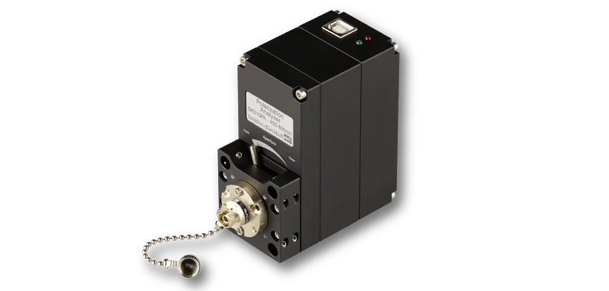
Measurement tool for coupling into polarization-maintaining fiber cables
Polarization-maintaining fiber cables
for collimating radiation exiting an optical fiber or as an incoupler
for coupling into single-mode and polarization-maintaining fiber cables