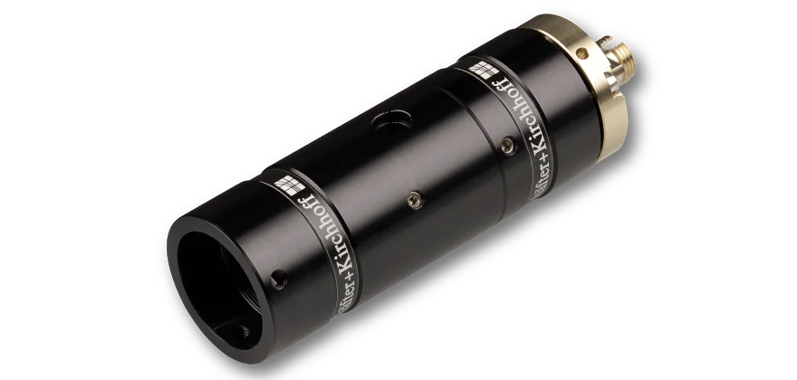
SK010PA-UV+

Measurement tool for polarization-maintaining fibers

SK010PA
SK010PA
SK010PA
SK010PA
SK010PA
SK010PA
SK010PA
SK010PA

Features

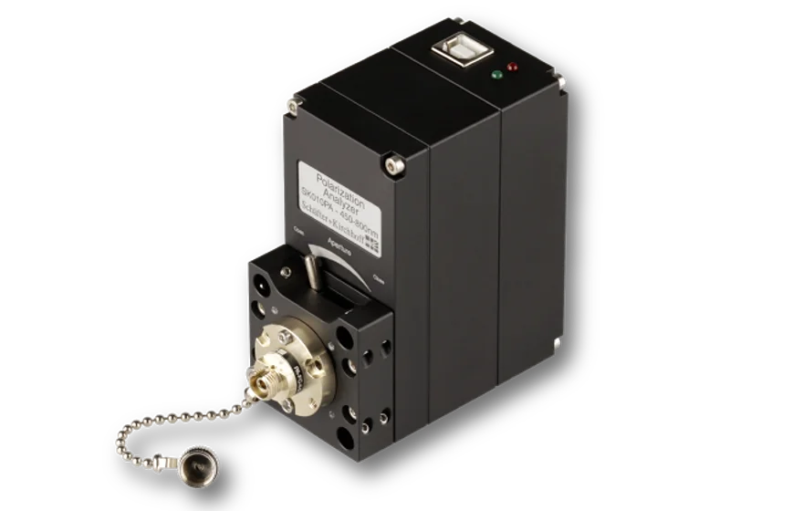
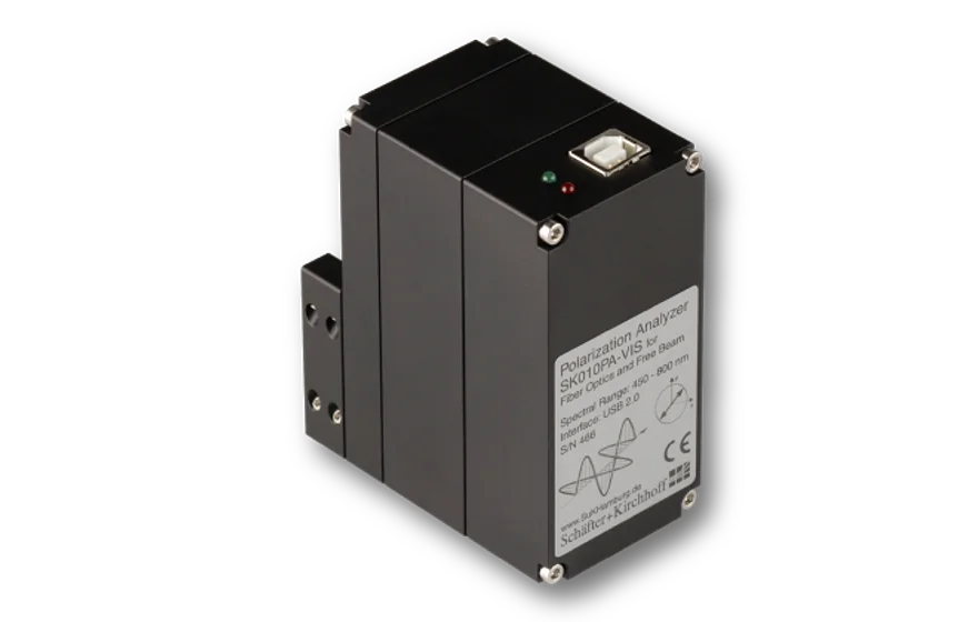
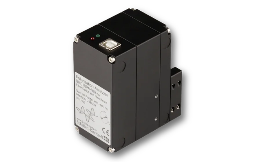
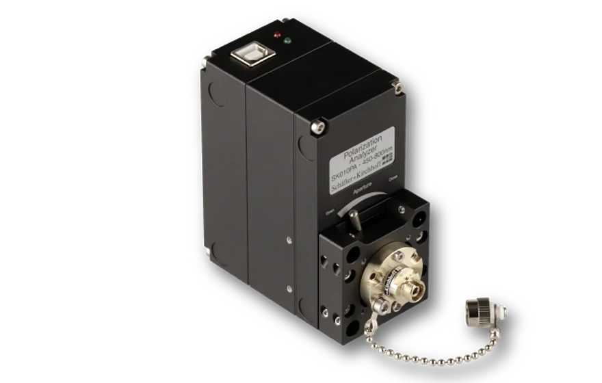
The Polarization Analyzer series SK010PA-UV+ are universal measurement and test systems for coupling laser beam sources into polarization-maintaining fiber cables. It is designed to work with wavelengths down to 350 nm.
  • Wavelength range 350 - 450 nm
  • USB 2.0-powered device (control, data transfer and power supply)
  • Determination of the state of polarization (SOP), with all four Stokes parameters, PER (Polarization extinction ratio), degree of polarization (DOP), ellipticity, etc.
  • Display of the SOP on Poincaré sphere or as polarization ellipse
  • Special routines for PM-fiber evaluation and polarization alignment
  • Compatible with microbench system, rail or cage system for free beam applications,FC APC adapter included for fiber applications

Description

The polarization analyzers SK010PA-UV+ (sometimes referred to as Polarimeters) are universal polarization measurement devices and test systems for coupling laser beam sources into polarization-maintaining fiber cables. They were developed from practical experience with a focus on high usability. It is designed to work with wavelengths down to 350 nm.

The polarization analyzer is a plug&play device and connects directly to the USB port of a Windows device. The device is compact and can be easily integrated within ­existing systems. Alignments and measurements are performed rapidly. A real-time measurement of the Stokes parameters is performed and shown in an interactive display that depicts the state of polarization on a Poincaré sphere.

Measurement method
The radiation coupled to the polarization analyzer is ­passed through a rotating quarter-wave plate and fixed polarizer before being recorded by a photodetector. The software SKPolarizationAnalyzer evaluates the Stokes parameters retrieved from a detailed analysis of the photodiode signal and the time/position information of the quarter-wave plate. The state of polarization is then depicted on the Poincaré sphere, where any change in the state of polarization including the direction of rotation (depicted on the northern or southern hemisphere) is easily visible.

Polarization Alignment for Coupling into PM fibers
The SK010PA Polarization Analyzer provides procedures for the optimization of the alignment of the incoming polarization direction of the source with the polarization axes of the fibers and for the measurement of the resulting Polarization Extinction Ratio (PER).

The procedure starts with the recording of exit polarization states while the temperature is changed, or the fiber is carefully bended, to cause the exit polarization to fluctuate. A circle is then automatically fitted to the data points on the Poincaré sphere, and the mean and minimal PER are displayed.

The radius of this circle indicates the quality of the ­alignment, since it shows the angle deviation between the fiber ­polarization axis and the polarization axis of the incoming radiation. For an optimally aligned ideal fiber, the data circle converges to a single point, the center of the circle.

In the example shown, the circle on the Poincaré sphere has a large radius. During continuous measurement of the exit polarization state, the fiber axis is then rotated with respect to the polarization axis of the laser source. The optimum alignment is reached when the exit polarization state approaches the circle center on the Poincaré sphere as far as possible.

A second measurement then reveals the parameters of the optimized polarization alignment of the fiber.

Free Beam Measurements
The polarization ­analyzer can also be used for ­setting a well-defined state of polarization for free-beam applications. For these type of measurements, a correct alignment of the laser beam axis with the polarization analyzer is essential. This can be done using the microbench, or 40 mm cage system and using the connection with 4 rods or the rail system.

Adjustment of Quarter-Wave Plates
The SK0101PA Polarization Analyzer can be used to align and quantify retardation optics, e.g. fiber collimators with integrated quarter-wave plates. For these collimators, the outcome polarization is adjusted by rotating the quarter-wave plate. Circularly polarized light is set when the poles are reached, with right-handed circular polarization located at the north pole, and left-handed polarization located at the south pole.

Standard delivery
  • SK010PA-UV+
  • USB cable
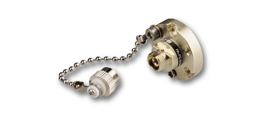
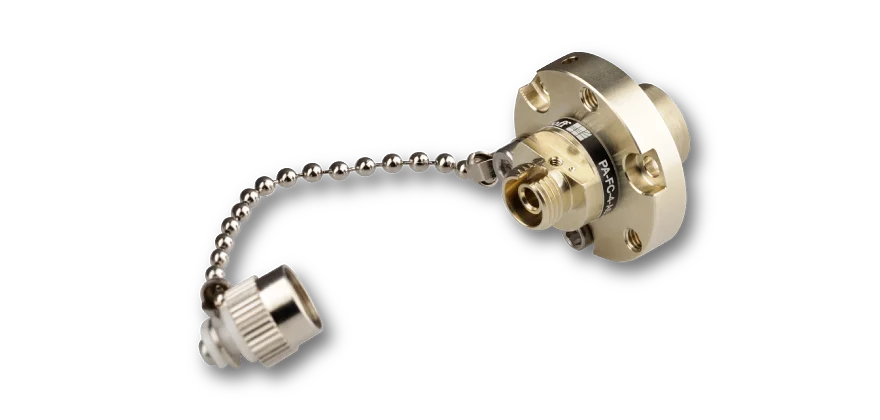
  • Adapter for wide key fiber connectors of type FC APC PA-FC-4-0
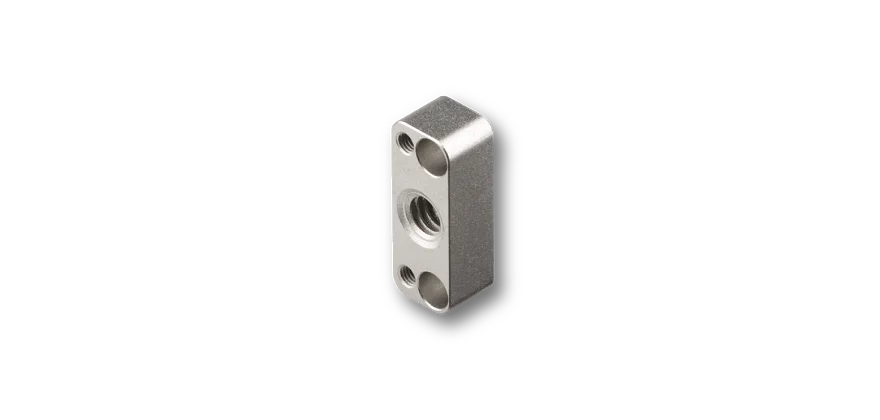
  • Adapter for post-mounting PA-AP-M4
  • Operating software: SKPolarizationAnalyzer for Windows 11/10 (32/64 Bit)
  • DLLs


Technical data

SK010PA-UV+

Order Code
SK010PA-UV+
Wavelength range
350 - 450 nm
Interface
USB 2.0
Power Supply
via USB
Fiber adapter
FC-APC (standard)
Free beam diameter
max. 4 mm
Power range
0.01 - 50 mW
Sampling rate
15 Hz
SOP accuracy
± 0.4°
PER accuracy
PER dependent, 0.5dB @ 25dB
DOP accuracy
5%
Warm-up time
5 min
Housing
40x70x82 mm (WxLxH)
Temperature range
10 - 36 °C
System requirements
Windows 11/10 (32/64 Bit)
Weigth
390 g

FAQ

  • General Questions
    • How is the polarization defined? Along or opposite to the direction of propagation?
      The polarization of the beams is defined opposite to the direction of propagation.
    • Can I use the Polarization Analyzer for free beam measurements and for PM fiber coupling?
      Yes, the Polarization Analyzer is suitable for both applications. Standard delivery includes an FC APC adapter, so that the PM fiber cable can be directly attached to the device. For free beam applications the Polarization Analyzer is compatible with the microbench system, rail or cage system.
    • What is the standard delivery?

      The standard delivery includes:

      • SK010PA of choice
      • USB cable
      • Adapter for wide key fiber connectors of type FC APC PA-FC-4-0
      • Adapter for post-mounting PA-AP-M4
      • Operating software: SKPolarizationAnalyzer for WINDOWS7, WINDOWS 10, WINDOWS Vista/XP (32/64 Bit)
      • DLLs

    • Do I need a separate power supply for the SK010PA?
      No, a separate power supply is not necessary. The SK010PA Polarization analyzer is powered by your PC via USB (USB 2.0). 
    • How do I mount the Polarization Analyzer. What are the possibilities?
      The Polarization Analyzer is compatible with the microbench system, rail or cage system for e.g. free beam applications.  An M4 post-mount adapter is supplied within the standard delivery of the Polarization Analyzer, to mount the analyzer on a post-mount with M4 thread. Other adapters with other thread diameters are available as accessory.
    • How do I connect the Polarization Analyzer?
      The Polarization Analyzer is a plug&play device and connects directly to the USB port of a Windows computer.
    • I have not installed the SKPolarizationAnalyzer software. Can I download it somewhere?
      Yes! Please download it from the Downloads section or from the SKPolarizationAnalyzer webpage (for registered users only).
    • Where do I find more information on the SKPolarizationAnalyzer software?
      Please visit the SKPolarizationAnalyzer webpage for more info. You can also find additional information in the Polarization Analyzer manual (available in the Downloads section).
    • How precise is the PER measurement?
      Assessing the accuracy of the PER measurement is not trivial. It is itself PER dependent and increases disproportionately with PER value. For a typical PER of 25 dB, the PER measurement accuracy can be given to be ± 0.5 dB.
      PER Measurements with values above 35 dB have a much larger measurement inaccuracy in the order of already a few dB and should not be taken too literally.
    • I want to measure a free beam? What do i need to think about?
      If you use the SK010PA Polarization analyzer with a collimated beam, the beam has to be aligned with respect to the system better than Â± 3°. Otherwise you will get implausible results.
    • What is the input beam power measurement range?
      The power range of the SK010PA Polarization analyzer is 0.01 - 50 mW. You can reduce the input radiation by using the integrated iris diaphragm in the front part of the Polarization Analyzer.
    • Does the Polarization Analyzer need annual calibration?
      There is no need for an annual calibration.
      However S+K offers to service the SK010PA Polarization Analyzers. This service includes an updated calibration report.

    • Does the Polarization Analyzer work with pulsed sources?
      Yes and no.
      The system operates with a measuring frequency of 15 Hz. If the pulse rate of your laser is much faster you can measure the polarization of a pulsed laser.

       
      However, the PER measurement of a PM fiber does work with a CW laser only.

    • What is the measurement frequency of the Polarization Analyzer?
      The system operates with a measuring frequency of 15 Hz. This value is intrinsic to the device and cannot be changed or read-out.
    • There are two adapter options - one without integrated optics and one with integrated optics. What is the best option for me?
      For standard applications we recommend to use an adapter without optics since any additional optics may show birefringence and so may falsify the measurement result.
    • Can I use two Polarization Analyzers with a single computer at the same time?

      Sometimes it might be necessary to have two Polarization Analyzers working at the same time with the same computer. This is possible.

      Several polarimeters can be addressed simultaneously using the DLLs. Depending on the order of connection, these receive different IDs via which they can be addressed specifically.
  • Questions about the Fiber PER Measurement Procedure
    • What does the value min PER mean?
      The min PER results from the worst possible state of polarization (SOP)  possible with the current setup. It is the point farthest from the equator. Thus, this value considers both the radius of the circle AND the distance of its center from the equator. More information can be found here.
    • What is the difference between lin. PER and PER?

      The extinction ratio PER is the ratio of the powers in the two (linear) principal states of polarization in logarithmic scale. 

      The extinction lin. PER is the ratio of linear polarized light to the total amount of light measured in logarithmic scale. For depolarized sources the lin. PER will be lower than PER.  

      You cannot caculate the PER from the lin. PER and vice versa.

      For coherent light sources (like e.g. most lasers) you need to use PER to optimize the polarization adjustment of the fiber.

      So what do you need the lin. PER for?

      The lin. PER is used to align the polarization axes to a source that has low coherence. In this case, the coherence is less than the difference in time it takes to pass through the fiber in the two principal axes of the fiber. In such a case, the value lin. PER serves as a measure of the polarization alignment. The larger the value lin. PER, the better the alignment.


    • When do I use the value lin. PER?
      The lin. PER is used to align the polarization axes to a source that has low coherence. In this case, the coherence is less than the difference in time it takes to pass through the fiber in the two principal axes of the fiber. In such a case, the value lin. PER serves as a measure of the polarization alignment. The larger the value lin. PER, the better the alignment. 

  • Trouble Shooting
    • The signal power is to low. What can I do?
      • Have you checked if the aperture is open?
        Please check if the mechanical aperture on the front of the device is opened completely. Open the aperture to increase the signal intensity.
      • Is your laser power too low?
        Please check your laser power and make sure it is above the minimum power level required for using the Polarization Analyzer. Adjust the laser power if possible.
      • Are you using the Polarization Analyzer for a free beam measurement?
        If yes, please make sure that the input beam is centric to the entrance aperture.
    • The signal intensity is too high. What can I do?
      • Have you closed the entrance aperture yet?
        Try closing the iris diaphragm at the Polarization Analyzer's entrance to reduce the signal intensity.
      • Is it possible to reduce the laser power?
        Please check if is possible to reduce the laser power. Keep in mind that laser properties may change if the laser power is reduced in such a way that the laser operates near the laser threshold. In case of laser diodes, this can e.g. cause polarization fluctuations.
    • I want to mount the Polarization Analyzer to an optical table. How do I do that?
      • Please check the standard delivery for the Post-mount adapter.
        Use the post-mount adapter supplied within the standard delivery of the Polarization Analyzer to mount the analyzer on a post-mount with M4 thread. Other thread diameters are available as accessory.
    • The measurement of the azimuth angle phi does not seem correct. What can I do?
      • Have you checked if the displayed angle is the relative angle?

        There are two setting for the angle of polarization Phi: absolute and relative. If the measured angle of linear polarization seems to be off, e.g. vertically polarized light is measured with an arbitrary angle to the vertical alignment of the device, then the setting might be set to "relative".

        Please check, if the angle of polarization Phi is displayed with the suffix “rel.”. Then change the setting from a relative angle to default setting via “Edit” -> “Set Azimuth (default)”.

    • The state of polarization for a free beam measurement seems to give implausible results. What can I do?
      • Have you checked the alignment of the Polarization Analyzer to the incoming laser beam?
        An incidence-angle of the incoming laser beam relative to the analyzer can lead to implausible results. Try to align the beam (or the Polarization Analyzer) to minimize the incidence angle. It should be ≤ ±3°.
    • The red LED on top of the Polarization Analyzer is flashing.
      • What does that mean?
        Unfortunately that means a failure of electro-mechanical components inside the device. Please contact Schäfter+Kirchhoff immediately and request an RMA.
    • My Polarization Analyzer is not recognized by software, even though there is a Polarization Analyzer listed in the Windows Device Manager. What can I do?
      • This sounds like an FTDI driver problem.
        Due to the widespread usage of USB-Communication chips of the same type in different measurement devices it is possible that a driver of another device changed the so called virtual COM-port setting of the Polarization Analyzer. This can be undone quickly. Please contact Schäfter+Kirchhoff to receive the corresponding technical instructions.
  • Polarization Analyzer accessories
    • There are two adapter options - one without integrated optics and one with integrated optics. What is the best option for me?
      For standard applications we recommend to use an adapter without optics since any additional optics may show birefringence and so may falsify the measurement result.

Downloads

STEP model
090721300125.stp (STEP model)
STEP model
090721300125.stp (STEP model, for registered users only)
Dimensional drawing
090721300125.pdf (Dimensional drawing)
Software file
SKPolarimeter_4_6_4.zip (Software file)
Software file
SKPolarimeter_4_6_4.zip (Software file, for registered users only)
Software file
SKPolarimeter_x64.zip (Software file)
Software file
SKPolarimeter_x64.zip (Software file, for registered users only)
Manual
Manual_Polarimeter_464e.pdf (Manual)
Manual
Manual_Polarimeter_464e.pdf (Manual, for registered users only)
Technote
Article_PolarizationAnalyzer.pdf (Technote)
CE icon
Conformity_SK010PA_2023_E_web.PDF (CE certificate)

Benefits of user registration include

  • Extended information for download including stepfiles, software or manuals
  • Direct download of user-specific downloads (e.g. user-specific software)
  • Access to previous online requests and the possibility to add complete previous lists to the "Request for quote" list
  • Stored item list
Click here to register.

Accessories

Polarization Analyzer adapters for post-mounting
to use with SK010PA Polarization Analyzers
Polarization Analyzer adapters for fiber cables without optics
to use with SK010PA Polarization Analyzers
Polarization Analyzer adapters for fiber cables with optics
to use with SK010PA Polarization Analyzers
SKPolarizationAnalyzer
Software for the SK010PA Polarization Analyzer